Recommended: Switching to S1U2
The UX410 terminals are no longer available for new orders. We recommend ordering S1U2 terminals.
If you are currently using UX410 terminals, we recommend switching to S1U2 terminals.
For more information, contact your Account Manager.
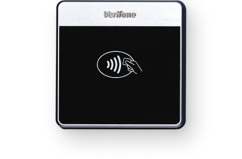
The UX410 payment terminal allows shoppers to pay with a contactless card or a mobile wallet by tapping their card or phone on or near the NFC-reader. Instead of a display, this terminal has indicator LEDs, an illuminating contactless logo, and a dual-tone buzzer to indicate the progress of the payment and other events.
The UX410 payment terminal consists of two separate devices:
- UX410 NFC-reader (also called antenna unit)
- UX410 controller unit
These devices are intended for mounting in a self-service machine such as a vending machine, coffee machine, token dispenser, or parking payment system.
Get started
Get your new unattended terminal up and running:
- Assign the terminal to your store.
- Inspect the terminal.
- Install the terminal.
- Monitor the boarding process.
There are four LEDs above the contactless logo. LED 4 is to the right of the logo. When LED 4 is blinking slowly, you are ready to process payments!
Supplied components
- UX410 NFC-reader
- UX410 Controller unit
- Clamping plate and four M4 washers and nuts to secure the reader
- RJ45 communication cable
- SMA (RF) antenna cable
- Power cord/adapter
Dimensions
| Component | Device dimensions | Cutout dimensions |
|---|---|---|
| UX410 NFC-reader | Height 80mm x Width 80 mm x Depth 16mm | Height 61.2mm x Width 73.2mm |
| UX410 controller | Height 90mm x Width 100mm x Depth 34mm | (none) |
For the NFC-reader, the front of the self-service machine must have an installation panel of about 2mm thick with a cutout and 4 mounting holes.
Assign the terminal
During the installation, the UX410 terminal obtains its configuration by boarding itself to your store. Contrary to most other terminals, you always need to assign an unattended terminal to a store before boarding the terminal.
-
Assign the terminal to your store using your Customer Area or using API calls.
In the procedure, use the serial number of the controller unit. You can view the serial number in your Customer Area, under In-person payments > Orders and returns, in the order for your terminal.
Inspect the terminal
Como os terminais processam dados confidenciais do cartão, é importante garantir que o terminal que você recebeu seja o terminal Adyen correto e que não tenha sido adulterado. Se alguma das seguintes verificações falhar, entre em contato com nossa Support Team imediatamente.
-
Verifique se a caixa que contém o terminal não foi aberta e se o selo de segurança está intacto.
O selo de segurança é uma etiqueta vermelha com um código de barras e um número, colada na tampa da caixa. -
Se você tiver acesso à Customer Area da Adyen, faça o login e, em Point of sale, localize o pedido do seu terminal. Então:
- Verifique se o terminal serial number (S/N) na caixa é igual ao da área do cliente.
- Verifique se o security seal number na caixa é igual ao da área do cliente.
-
Usando as informações de track & trace na área do cliente, acompanhe o pedido com a transportadora para verificar se eles confirmam a entrega do terminal de pagamento.
-
Quebre o selo de segurança, retire o terminal da caixa e verifique se o terminal serial number (S/N) no próprio terminal é o mesmo que o número de série na caixa.
-
Inspecione o terminal quanto a adulteração. Verifique se faltam vedações ou parafusos, fios ou etiquetas adicionais, orifícios no dispositivo e qualquer coisa inserida ou conectada a qualquer parte do terminal, como o leitor de cartões ou as portas.
Install the terminal
Apart from the supplied components, you will need at least:
- 8 bolts, washers, and nuts to secure the clamping plate and the controller unit inside your self-service machine.
- Installation instructions form the manufacturer of your self-service machine.
Proceed as follows:
-
Mount the NFC-reader to the front of the installation panel.
- Remove the protective film from the back of the NFC-reader.
- Place the stud bolts of the NFC-reader through the holes in the front of the installation panel.
- At the back of the installation panel, place the flat side of the clamping plate over the stud bolts.
- Secure the NFC-reader using the four supplied M4 washers and nuts to a torque of 0.7 Nm.
- Secure the clamping plate to the installation panel.
-
Remove the protective film from the front of the NFC-reader.
-
Secure the controller unit inside the self-service machine near the NFC reader, using 4 bolts, washers, and nuts to a torque of 0.7 Nm.
Do not install the controller unit inside a chassis that can be removed from the self-service machine.
-
Connect the NFC reader to the controller unit.
- Connect the SMA (RF) cable to the back of the NFC-reader and to the RF port on the bottom of the control unit.
-
Connect the RJ45 cable to the back of the NFC-reader and to the COMM port on the bottom of the control unit. Do not use the COM1 port.
The RF port and the COMM port are located next to each other on the bottom of the control unit, and are marked ANT.
-
Connect an Ethernet cable between the LAN port on the controller unit and your network.
Only connect a regular Ethernet cable to the LAN port. Using any other type of cable or another port, such as the COM1 RS232 port, might severely damage the device.
-
Connect the power cord between the DC IN port on the controller unit and a power supply unit in the self-service machine or an external power source.
The controller beeps. After approximately a minute, a green light and an amber light on the LAN port turn on. The terminal starts boarding.
Monitor the boarding process
When you finish the installation, the UX terminal starts up, connects to the network, and boards itself to your store. The LEDs indicate the steps in this process.
The steps may go too fast to follow. But if an issue occurs, the LEDs indicate the step where the process has stopped:
-
The terminal tries to connect to your network:
LED 1 LED 2 LED 3 LED 4 Description Blinking On On On No network -
The terminal has connected to your network and now tries to connect to our platform:
LED 1 LED 2 LED 3 LED 4 Description Off Blinking On On No connection with the plataforma de pagamentos da Adyen -
The terminal has connected to our platform and now tries to board itself to your store:
LED 1 LED 2 LED 3 LED 4 Description Off Off Blinking On Not boarded The terminal will stay in this state if it hasn't been assigned to a store (or merchant account representing a store).
-
The terminal has boarded and is ready to accept payments:
LED 1 LED 2 LED 3 LED 4 Description Off Off Off Blinking slowly Ready
If boarding doesn't succeed, the terminal will try again after two minutes. Remember that the terminal can only board if it is assigned to your store.
After ten retries, the terminal stops trying to board. You cannot tell it has stopped trying; LED 3 continues to blink and LED 4 remains on. You can trigger the boarding process again by disconnecting the controller unit from the power source, and then connecting it again.
Other LED signals
During the boarding process, the LEDs indicate the progress. There are various other events and situations that are also indicated with LED signals. We describe a few of them here.
Payment
The terminal has received a payment request and is ready for the shopper to tap their card or phone to the NFC-reader:
| LED 1 | LED 2 | LED 3 | LED 4 | Description |
|---|---|---|---|---|
| On | Off | Off | Off | The CTLS logo also lights up |
The shopper has tapped their card or phone and the NFC-reader has read the card details:
| LED 1 | LED 2 | LED 3 | LED 4 | Description |
|---|---|---|---|---|
| On | On | On | On | The buzzer also sounds |
Error
The terminal has failed to load its keys and needs to be replaced:
| LED 1 | LED 2 | LED 3 | LED 4 | Description |
|---|---|---|---|---|
| Off | Off | On | On | Keys not loaded |
Red light
A red LED 1 indicates a warning. The terminal may have been tampered with.
- Stop using the terminal and contact our Support Team immediately.